This is one that I’ve been excited about for a long time. When element14 asked me to put together a holiday special, I knew just what to do. This episode is the most technically complex so far; it covers non-inverting op-amp circuits, low-pass envelope detection filters, buffers, power management, and some clever programming. Because of the complexity of the project, fellow Cornell Engineer, Brian Schiffer (whom you might remember from this article where we were both featured) co-hosted this tutorial with me. The end result is pretty spectacular – a chain of 50 LEDs reacting dynamically to music. The twist, however, is that the chain propagates color information from the center, resulting in a temporal visualization of the music. The schematics, programs, and parts list are available for download below:
You can download the files associated with this episode here: Arduino Tutorial 14 Files
Source materials for all my arduino tutorials can be found in my github repository.
![]() Distributed under the GNU General Public (Open-Source) License.
Distributed under the GNU General Public (Open-Source) License.
Please Attribute and Share-Alike.
Update (9/2/2013): The code has been updated to reflect the new naming convention for the Adafruit LED Library.
Update (12/18/2012): Check out this system installed in a Car by Gyurma
Update (12/15/2012): The Adafruit Library has been updated, and will necessitate a small change to the code. Check out this comment thread for more info.
Update (12/2/2012): Some viewers have suggested improvements to this circuit that have worked well. If you’re having troubles with the circuit I presented, try out this circuit, by John Basila. Open Source Education wins again!
Update (6/9/2012): Check out this version made by Steved: http://youtu.be/iYxLQxpBTJ8
168 comments
Jeremy,
Could you explain more about the [LED Freq Control.pd] included in the zip file. Is that a Processing file? Thanks.
No, that’s a puredata file. I show it in the video. It’s just a simple script for generating arbitrary frequency sine waves from your sound card. Visit http://www.puredata.info to download puredata.
Hi, all of this you are doing is great, thanks for allow all of us learn from your experience, I have a question, are you going to do any tutorial about gyroscopes or acellerometers some day?, thanks
Yes, eventually – I have a very long list of tutorials that I’d like to do. But, most gyros and accelerometers are either analog outputs, I2C, or SPI, all of which I’ve done tutorials on. So that should be enough to get you started.
Hello jeremy blum
That was a great electronic project. I was able to open the code but i could not compile and upload. It gave me error. Here is the error “Ws2801 does not a name type”.
Did you add the WS2801 Library to your arduino library folder?
yes, i downloaded the zip drive from https://github.com/adafruit/Adafruit-WS2801-Library. I put it on the desktop. What do you mean “add the WS2801 Library to your arduino library folder”. You mean put it inside the arduino zip drive 1.0 that i downloaded from arduino.cc
I have already tried. The code still give me the same error. Tell me what did i miss? Thank you.
You need to unzip it, and put the folder in the unzipped arduino application library folder. Follow this guide: http://www.ladyada.net/library/arduino/libraries.html
That was very helpfull. It works now. Thank you for letting us learn. Happy new you.
Have a happy, safe, and prosperous New Year.
Hello I’m Mark from Philippines. I watched your videos regarding arduino. It’s actually interesting. I also watched some arduino+android projects in youtube. I am graduating (ECE) student….got problem with our undergrad thesis. We are planning to make android plus arduino project…don’t know how to start…
Can you help me with this?
Your HELP is much appreciated!
Tnx and GOD Bless!
I don’t yet have an experience interfacing the arduino with android devices.
No problem…Tnx!
Jeremy, could you post some video controlling arduino throght the internet? I have an Ethernet Shield but i’m facing problems with this.
I’m planning to. Not sure when Ill get to it, though.
I hope it will be soon!
Hi
I am a huge fan and this tutorial got me super stoked. I did hit a snag though. I built out the breadboard from your awesome diagram. I think I got it right but the two 5mm LEDs light up as soon as I supply power to the LM324. If I unplug the audio and the wires from the arduino (except for power) they still light up by default. Even without audio and even if I totally remove the potentiometers entirely the bulbs stay on. If I adjust the potentiometers the lights barley respond by going just a bit dull but they stay on. I know how hard it is to troubleshoot something you can’t see but every clue helps. So the question is: why are my LEDs on by default? Any clues? Thanks again for all your hard work and for the record this tutorial caused me to make my first order from element 14 and my LEDs are on the way from Ladyada.
Got it working. Turns out that it the two LEDs will default to on unless there is an audio signal present. The audio jack in the parts list did not have a firm connection to the breadboard. Once I put together a better connection for the audio jack an LED started pulsating on one channel. Still working on the second channel.
Thanks again for the great tutorial!
Great news! Be sure to share a video when it’s complete, and let @element14 and @adafruit know on twitter that you’re using parts from their sites to make it!
I have been following your blog for some time now. And I love every on I have seen. I have been out of the design side of engineering for quite some time now and never came close to mastering programming (the closest I ever came was on a VIC 20) if that gives you some idea of how far I have to go. which brings be to my question…. controlling multiple servos/ motors seems to have me stumped… how do you assign and control two or more???
Its possible, but since a system timer is taken over to control the duty cycle of each servo, you need to detach() one servo before you can control another.
Hi Jeremy, I know that this question does not apply to video lesson.
Could you help me to upload AFMotor libriuary on my Arduino 1.0?
Thanks in advance!
I’m a fan of you
Follow this guide: http://www.ladyada.net/library/arduino/libraries.html
Hello Jeremy
I have a question for you
Whats whith this program?
sketch_jan24a.cpp: In function ‘float ping()’:
sketch_jan24a:17: error: ‘pingPin’ was not declared in this scope
sketch_jan24a:25: error: ‘microsecondsToInches’ was not declared in this scope
sketch_jan24a.cpp: In function ‘void forward()’:
sketch_jan24a:34: error: expected `;’ before ‘motor4’
sketch_jan24a.cpp: At global scope:
sketch_jan24a:45: error: expected constructor, destructor, or type conversion before ‘direction’
#include
AF_DCMotor motor1(1, MOTOR12_8KHZ);
AF_DCMotor motor2(2, MOTOR12_8KHZ);
AF_DCMotor motor3(3, MOTOR12_1KHZ);
AF_DCMotor motor4(4, MOTOR12_1KHZ);
void setup() {
Serial.begin(9600);
motor1.setSpeed(200);
motor2.setSpeed(200);
motor3.setSpeed(200);
motor4.setSpeed(200);
}
float ping()
{ // This is the code that runs the PING)) Sensor
long duration, inches;
pinMode(pingPin, OUTPUT);
digitalWrite(pingPin, LOW);
delayMicroseconds(2);
digitalWrite(pingPin, HIGH);
delayMicroseconds(5);
digitalWrite(pingPin, LOW);
pinMode(pingPin, INPUT);
duration = pulseIn(pingPin, HIGH);
inches = microsecondsToInches(duration);
return inches;
}
void forward()
{
motor1.run(FORWARD);
motor2.run(FORWARD);
motor3.run(FORWARD)
motor4.run(FORWARD);
}
void backward()
{
motor1.run(BACKWARD);
motor2.run(BACKWARD);
motor3.run(BACKWARD);
motor4.run(BACKWARD);
}
voidhaltMotors()
direction.)
{
motor1.run(RELEASE);
motor2.run(RELEASE);
motor3.run(RELEASE);
motor4.run(RELEASE);
Read the errors – they tell you exactly what is wrong. You never set PingPin to a value before trying to set it as an output pin. The same is true for microseconds to Inches. You need to declare it be fore you use it. You are missing a semicolon in your forward() function.
hey Jeremy sweet videos i knew nothing about the arduino but have always wanted to build a autonomous/RC tank out of my old Heng Long tank and it would not have been posible with out you help so thank and also are there going to be any new arduino videos coming soon thanks again
ROBOT Dave
I’m always working on new videos – I’m busy with a lot of other things too.
Dear Jeremy, I’m a novice programmer when it comes to Arduino. I came up with the idea to make a clock based on something I’d seen before, a 60 RGB led clock, powered by an Uno r3, a LDR, a DS1307 (to be swapped by a Chronodot) and 60 LPD6803 led’s. It’s light intensity depends on the surrounding light. The clock works but not flawlessly… Green represents hours, red minutes en blue seconds. The seconds use 3 LED’s (first fading in, last fading out) to make the blue light gently move.
The clock uses the 1KHz SQW as an interrupt.
Is it the way I use the interrupt? Or is it simply to much for the Arduino? Should I skip the brightness control? Is the code written efficiently?
Here’s a video. The clock seems to work okay, but it’s not! It chrashes randomly…
http://www.facebook.com/photo.php?v=2972701567528&set=vb.1561464916&type=2&theater
Here’s the code. Can you have a look and help me on this one…
/*****************************************************************************/
// LPD6803 lib from ladyada
#include “LPD6803.h”
// LPD6802 pins
int dataPin = 11; // ‘green’ wire
int clockPin = 12; // ‘blue’ wire
// Don’t forget to connect ‘yellow’ to ground and ‘red’ to +5V
// LDR pin
int LDRPin = A2;
// Timer 1 is also used by the strip to send pixel clocks
#include
// Set the first variable to the NUMBER of pixels. 60 = 60 pixels in a row
LPD6803 strip = LPD6803(60, dataPin, clockPin);
//wire and rtc
#include
#include “RTClib.h”
// RTC_Millis is for a soft rtc
//RTC_Millis RTC;
RTC_DS1307 RTC;
// Define second, minute, hour
int s;
int m;
int h;
// Brightness fade up (1 or 2) depens on LDR reading
int z;
// Set brightness min 6, max 31.
int MinBright = 6;
int MaxBright = 31;
int brightness;
// LDR
int LDRValue;
void setup() {
Serial.begin(19200);
//start wire and rtc
Wire.begin();
RTC.begin();
{
//Serial.println(“RTC is NOT running!”);
// following line sets the RTC to the date & time this sketch was compiled
RTC.adjust(DateTime(__DATE__, __TIME__));
}
// set 1hz sqw on DS1307 pin 7, we will using this for a interrupt on arduino pin 2
Wire.beginTransmission(0x68); // write the control register
Wire.send(0x07); // register address 07H)
Wire.send(0x90); // 0x90=1Hz, 0x91=4kHz, 0x92=8kHz, 0x93=32kHz
Wire.endTransmission();
// The Arduino needs to clock out the data to the pixels
// this happens in interrupt timer 1, we can change how often
// to call the interrupt. setting CPUmax to 100 will take nearly all all the
// time to do the pixel updates and a nicer/faster display,
// especially with strands of over 100 dots.
// (Note that the max is ‘pessimistic’, its probably 10% or 20% less in reality)
strip.setCPUmax(90); // up this if the strand flickers or is slow
// Start up the LED counter
strip.begin();
// Update the strip, to start they are all ‘off’
strip.show();
//Attach pin 7 from DS1307 to Arduino pin 2 and call function clock
attachInterrupt(0, clock, FALLING);
}
// Empty loop, all is done by the 1hz interrupt on pin 2
void loop () { }
void clock() {
interrupts(); //start all interrupts again.
//attach Interrupt stops the strip, so start it again
strip.begin();
//Get current time
DateTime now = RTC.now();
// mapping hour 24 => 12 => 60 (hour hand)
m = now.minute(), DEC;
s = now.second(), DEC;
h = now.hour(), DEC;
if (h >= 12) { h = h – 12; }
else if (h = 12) { h = 0; }
h = map(h, 0, 12, 0, 60);
if ( m <= 6 ) { h == h; }
else if ( m <= 18 ) { h = h + 1; }
else if ( m <= 30 ) { h = h + 2; }
else if ( m <= 42 ) { h = h + 3; }
else if ( m <= 54 ) { h = h + 4; }
// Get LDR vaulue and set brightness
LDRValue = analogRead(LDRPin);
brightness = map(LDRValue, 0, 1023, MinBright, MaxBright);
// set increase step
if ( brightness 0
if (s == 0) { strip.setPixelColor((58), 0, 0, 0); }
if (s == 1) { strip.setPixelColor((59), 0, 0, 0); }
if (m == 0) { strip.setPixelColor((59), 0, 0, 0); }
//start fade up/down
for (int y = 1; y < brightness; y = y + z) {
strip.setPixelColor((s – 1 ), (brightness – y), 0, 0);
if (s == 0) { strip.setPixelColor(59, (brightness – y), 0, 0); }
strip.setPixelColor(s, brightness, 0, 0);
strip.setPixelColor((s + 1 ), y, 0, 0);
if (s == 59) { strip.setPixelColor(0, y, 0, 0); }
strip.setPixelColor(m, 0, brightness, 0);
strip.setPixelColor(h, 0, 0, brightness);
// second equals minute
if ((s + 1) == m) { strip.setPixelColor(s + 1, y, brightness, 0); }
if (s == m) { strip.setPixelColor(s, brightness, brightness, 0); }
if ((s – 1) == m) { strip.setPixelColor(s – 1, (brightness – y), brightness, 0); }
// second equals hour
if ((s + 1) == h) { strip.setPixelColor(s + 1, y, 0, brightness); }
if (s == h) { strip.setPixelColor(s, brightness, 0, brightness); }
if ((s – 1) == h) { strip.setPixelColor(s – 1, (brightness – y), 0, brightness); }
// update strip
strip.show();
delay(105 – (2 * y));
}
// Debug
//Serial.print(now.year(), DEC);
//Serial.print('/');
//Serial.print(now.month(), DEC);
//Serial.print('/');
//Serial.print(now.day(), DEC);
//Serial.print(' ');
//Serial.print(now.hour(), DEC);
//Serial.print(':');
//Serial.print(now.minute(), DEC);
//Serial.print(':');
//Serial.print(now.second(), DEC);
//Serial.println();
Serial.print("raw LDR reading = ");
Serial.println(LDRValue); // the raw analog reading
Serial.print("mapped brightness level = ");
Serial.println(LDRPin); // the analog level
Serial.print("brightness level = ");
Serial.println(brightness); // the calculated level
Serial.println();
}
/*****************************************************************************/
Hi Jeremy, have you ever minded to develop arduino on Qt creator? It would be awesome work to post a tutorial about that which includes building pro file, setting up libraries etc. even if it does not use qt library.
I used WS2801 library https://github.com/adafruit/Adafruit-WS2801-Library in the following program, however I still don’t know how to change the last 6 LED into red before turning them off. Even I don’t know whether it is possible or not. Can anyone let me know? I used the WS2801strip from http://www.bestlightingbuy.com/ws2801-addressable-rgb-led-strip.html
hi jeremy, you are doing a great job i learnt so many new things from you, your videos are simply awesome and your explonations are very neat , really u inspired me and i am very thank full to you for sharing your knowledge here.
and i have a question for you “how to write threading programs in arduino”?
Jeremy,
Home sick from work… Got bored.. Built the circuit, plugged it in turn signals that I’m building for my wires show car. 186 Ws2801’s rocking out to UB40. What a pisser! Worked perfect first time. Thanks!
Cool! Post pictures!
Sorry I was distracted by something shiny…
http://youtu.be/iYxLQxpBTJ8
Awesome! I’m adding a link into the post.
Trying to link some pictures.
http://sdunsmuir.net/pics/board.jpg
http://sdunsmuir.net/pics/board2.jpg
Great tutorial, but I can’t get your lights_take1 or 2 sketch to upload as I get the “does not name a type” error. Yes I downloaded the Adafruit_WS2801 library and put it where I normally do & the Arduino program finds it in the Sketch-Import Library dropdown
I note that you call the library “WS2801” rather than “Adafruit_WS2801”, so I have tried renaming everything I can think of, as well as putting a copy of the .h and .cpp files in folders like where your lights_take 1 is just to be sure, but no difference.
The strandtest from Adafruit loads fine. A couple of other lines of error mention “include Wprogram.h”, but I checked my SPI and Adafruit_WS2801 library H and CCP files and “include Wprogram.h” is there.
I am running Windows XP Pro & have rebooted & tried two different computers. I did just update from Arduino 2,2 to Arduino 1 as required, so might I need to uninstall the old version? I just copied my old libraries into the Version 1 libraries folder, so could old library files be causing a conflict? Do they need to be converted?
You Gents are doing wonderful work, thanks for helping an old guy. GCH
Success. The main issue is with the Version 1 IDE vs the 0022 I was using. The older SPI library won’t work because Wprogram.h has been changed to Arduino.h. The Adafruit_WS2801 H library addresses this by adding the code
#if (ARDUINO >= 100)#include #else #include
The SPI library with the new Version 1 zip download only has the Arduino.h entry so I assume it won’t work with earlier libraries, even though the new version sees them in the Import Library list, which opens the door of confusion. This renaming file extension monkey business is going to create lots of problems for novices like myself and is why us old guys say. “If it ain’t broke, don’t fix it.”
Even with the correct SPI library, the upload would hang at the Library Setup line so I changed the library name and line below Library Setup to exactly what is in the the Adafruit strandtest sketch. With that change, the upload worked and I got to play with making colored light with my Theremin rather than trying to learn to write code.
Very well written tutorial. Thanks again. GCH
Jeremy Blum.
hi
i can enable serial communication. without connected usb to arduino mega. i want use serial1 port
help me
thanks
Hi Jeremy,
A big thanks to you for providing us with excellent tutorials on Arduino.
I am actually trying to make a led audio visualizer out of this tutorial. The ADC is working perfect, but if I change the volume the ADC readings also go down proportionally. Even with the maximum gain there is less dynamic changes which I can see when I reduce the volume of the audio system (car audio system). Basically less input to the op-amp which implies less amplified output.
Is there a way to get rid of this volume dependency on ADC?.
Thanks in advance for your suggestion.
Iqbal
That’s the expected behavior, since we are measuring the amplitude of the input wave. You could handle it entirely in software by sampling for the max and min ADC inputs and scaling them appropriately.
Hi Jeremy,
Thank you for your prompt reply :). Its exactly what I have done to try to solve the issue :) (Now I feel like I am in the right path). Actually I looked on to some literature on the logarithmic perception of sound and converted my difference in ADC values to dbV and scaled them down to the required number of LEDs to light up. Even then at very low volumes I cant get more dynamic behavior, may be I am expecting too much ;).
If I could do this sampling before volume modification (which is inside the audio system) ,can I get what I want? (just to get to know)
Thanks a lot for your suggestion.
Iqbal
Hello Jeremy,
can you please help me with my project.
i want to control LEDs(8 or more) using Visual basic 6.0 to arduino.
i’m really confused writing the source codes.
i want to finish this and for my future project, i want to control relays and motors.
Thanks!
here’s my email to send the source codes: [email protected]
Did you create a shield or pcb? Do you have gerbers?
No, this was all done on the breadboard shown in the video.
Hi Jeremy,
I have made your project using a small LED strip from ada fruit. I am applying it to the bottom and seat tube of my bike to make a disco bike. I am trying to get everything down into a small package to be mobile,
My question is: can I power the arduino by connecting the arduino 5v pin to the same 5v line that powers the lights. I assume so, but I thought I might ask before I burn something out.
Cheers. Thanks for the vids. Loved EE basics.
Yes that will work.
Hi,
Thank you for a great tutorial. I have built the project with great success. I ran in to some issues with the op-amp getting trashed on high amplitudes (maybe I exceeded the -3v limit on the input pin?). A voltage divider and increased gain solved the problem. But my question regards the RC-circuit (low pass filter). As I understand it, high frequencies goes through the capacitor and short-cuts to ground. That’s fine. What I do not understand is when the capacitor is discharging “over the resistor”. What is this “magic” pull being done by the resistor? Also, it implies that the discharge goes backwards towards the resistor and not to vout. Please clarify this. Thank you.
I have noticed that although the schematic is correct that the resistor numbers don’t add up. You start with R4 and end with R10. What happened to R1-R3 or was this just an oversight ? I am redrawing the schematic and will provide you a copy of it to include in your ZIP file after you approve it.
It’s just because I deleted some components, then added new ones without resetting the numbering. Those are just ID numbers, they don’t have to be consecutive.
I would like to continue the question that Pierre posted.
I also am a little puzzled by the LPF placement, I think that the low pass filter should be moved and changed. It should be moved before the OP Amp buffer and changed by placing the 10K resistor to connect the output of the first OP Amp with the input of the buffer OP Amp and the capacitor connected between the input of the buffer OP Amp and ground. I think should make more sense.
Jeremy, can you please comment and correct us if we are wrong?
I think a correction should be in order.
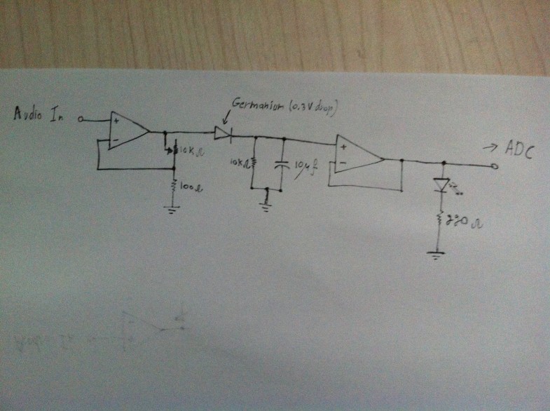
The Low Pass Filter is indeed placed incorrectly and missing one component. A rectifier (diode) should be added to the schema between the OP AMP and the LPF, this will insure that the charge will be done almost instantly when the voltage is greater than the voltage of the capacitor and when the voltage drops below the capacitor voltage, the capacitor will discharge through the resistor (the 10K resistor). The LPF and the rectifier (diode) should be placed between the to OP AMPs as follows:
From the output of the first OP AMP connect the rectifier, the second connection of the rectifier goes to the capacitor and resistor and then to the input of the second unity OP AMP.
I think this is the correct schema and I hope Jeremy will comment on this soon.
John, are you suggesting this setup? https://www.dropbox.com/s/9gfxddv0kza2atp/2012-12-01%2022.45.00.jpg
I agree this filter probably makes more sense, but I’m concerned about the impact of the voltage drop over the diode, and how it will affect the output amplitude. Why not just put this filter after the unity gain buffer (where it was) and loose the diode?
If there will be no blocking diode between the output of the op amplifier and the capacitor, the capacitor will discharge through the output of the OP AMP.
This is half of the problem, the capacitor will not only discharge though the 10k resistor, but will also discharge through the LED, thus changing the time constant of the discharge which was suppose to be 10K ohm * 10m F = 0.1 second. To make this work properly, the same LPF that was used needs to be placed before the unity OP amp and block the discharge though the first OP AMP output via a diode.
This is the diagram I was referring to:
https://docs.google.com/open?id=0B5U4J3bs167iWW9JZ1VFa3dlR0E
I would like to thank for this idea. I have created a PCB with these schematics and it’s a great success.
I see, thanks! Is the PCB you mentioned open source? I’d love to share it via a link from this post. Do you have any pics or video showing your setup in action. I’m going to add this schematic to this post.
I have created the PCB layout for an experimental PCB. The setup works perfectly. I’m providing the following two link for the Fritizing file that contains the PCB layout and the my sketch that was based on your sketch but ended up changing almost everything.
Please note that the power is connected directly to the LED Strip and from there, the 4 wires that connect to the PCB provide it with power. This, however, introduced a problem when the LED Strip started using the PWM. This caused noise to enter the circuit and was heard over the speakers. To resolve this, I added a 470mF capacitor on the power line on the PCB.
https://docs.google.com/open?id=0B5U4J3bs167iaVRXbHo5T2hBY28
https://docs.google.com/open?id=0B5U4J3bs167ieHhzajJnU3ptaHM
This is a picture of the PCB I built:
https://docs.google.com/open?id=0B5U4J3bs167iSGRIU3VIQjR0MEU
This is video, not a very goo quality, but just to give an idea.
http://www.youtube.com/watch?v=eJlW4opaixs
The things I had to fight with that made me work on improving the sketch were the music levels that can change causing a few colors to appear. To work around this, I have made changed the “constraint” and “map” function to be more dynamic. To be more exact I removed the constraint and gave the “map” function the maximum level based on the input read. When a new maximum level is read, it will replace the old maximum level. To allow lower input samples to also function properly, I added a “decay” functionality which lowers the maximum by 1 on each sampling cycle. For the minimum, which in you case was 0, I had also to do something similar. The lowest value can be above 0 when listening to a loud song (“gangnam style” should provide a good idea :)) which keeps the levels of input above 0. I did the same thing, I push the lower level up by 1 each cycle, and when a new minimum is read, i replace it with the old minimum. The code should provide the best explanation.
I had a few friends play with the new gadget and they gave me a very good feedback regarding the music synchronization with the pixels. When you view the center of the strip, you get the feeling that all is synchronized, but move away from the center and you get a delay. This is fine, but I wanted to think of a better display.
I came up with a “spectrum” like behavior. When reading an input, it will be always leveled between 0 – 255, I then map that to a value between 0-24 (half of the 50 pixel strip) and light only that pixel. I also added a fading effect to the pixel and the outcome is outstanding. If you get some free time, try my sketch and tell if you like the effect.
I also made the sketch go though the patterns I made.
I can’t upload your code :(
lights_take4.cpp.o: In function `loop’:
C:\Users\Gyurma\AppData\Local\Temp\build1224854618484674236.tmp/lights_take4.cpp:409: undefined reference to `__cxa_guard_acquire’
C:\Users\Gyurma\AppData\Local\Temp\build1224854618484674236.tmp/lights_take4.cpp:409: undefined reference to `__cxa_guard_release’
Will it work, if i delete static, from static unsigned long?
I use Arduino 0.22, because newer versions doesn’t work with my duemilanove
I just updated the sketch, please re-download it should compile on Arduino 0.22.
Thanks, now it’s uploaded :) now i’m going to test it, but i have a 25 pixel led stip, will it work with it good, or should i rewrite “const int length = 50” to something? maybe 26?
set it to 25 should do the work, but you will probably have the middle led off.
I would like to correct myself, please set the value to an even number. So please use 24, otherwise you will have a memory overrun.
Thanks, i will try it, now i’m mounting the led strip in my car :)
Do remember to post pictures and videos :)
Hi
Your project is great However I cant compile and upload the progam on ardunio version 1.0.3
Because it says this error ” ‘WS2801’ was not declared in this scope ”
please can I have some help
thanks, Daniel
Daniel,
When Jeremy wrote this episode, Adafruit, who wrote the WS2801 library used to call it WS2801. since then, they changed the library name to Adafruit_WS2801. You will need to download their library from here:
https://github.com/adafruit/Adafruit-WS2801-Library/archive/master.zip
After downloading the ZIP file, please open the content of the zip file and place them in the “libraries” directory of the arduino IDE you installed.
You will have to make a few adjustments to the sketch to make it compile, they are minor.
Change
#include “WS2801.h”
to
#include
Also, change
//Library Setup
WS2801 strip = WS2801(length, light_data, light_clk);
to
//Library Setup
Adafruit_WS2801 strip = Adafruit_WS2801(length, light_data, light_clk);
this will most likely resolve your problem.
The post was snapped, probably because i used a reserved character like the “smaller-than” :).
The fix to the sketch should be:
Change
#include “WS2801.h”
to
#include “Adafruit_WS2801.h”
Also, change
//Library Setup
WS2801 strip = WS2801(length, light_data, light_clk);
to
//Library Setup
Adafruit_WS2801 strip = Adafruit_WS2801(length, light_data, light_clk);
Thanks John!
This issue had me head-scratching for an hour, you should update the code on git asap to help others out :)
Thanks guys, I’ve updated the code repos and downloads to reflect this change.
Something is wrong, when i’m using your code, after 15-30 seconds the program crashes, please help me figure out why :( with jeremy’s program it doesn’t crash, but if i turn up the volume, it’s only green, and i need to turn the potenciometer to work again, but i don’t want to turn it every time…
Help is on the way :).
Let’s start by asking a few questions:
1. Have you modified my code (this includes commenting out lines)?
2. Did you try to set the CYCLE_DM to 0? Does this solve the problem? Try to set it to 5000 and see if the crash happens after 5 seconds.
I have a wild guess here, but it’s a wild guess: Have you by any chance commented out something in the g_displayModes[] array? To be more exact, did you comment out the last line and you have an extra comma at the end of the last line in the array that is not commented out?
Can you please send me your sketch if you modified it? you may e-mail me at [email protected]
I only modified the “const int length = 50” to 26, and also tried with 24. I will try setting CYCLE_DM, but i can’t test it today
but i also tried without modifying anything in the code
Oh, i watched your video, its not a crash, its an effect, at 0:46 :D it’s just very wierd with 25 leds :D Setting CYCLE_DM to 0 solved the problem, now it works fine. Thank you :) i will upload a video
I’m glad it worked out.
Feel free to try out all of the effects, they are documented in the sketch.
To try them, simply make sure you don’t have any commented out effect in the g_displayModes[] array, set the CYCLE_DM to 0 and chose the effect you would like to run by setting the value of “g_displayMode” to a number between 0 and 4.
I do have a question though, did you build a PCB for this? can you share a picture or two?
Loving the collaboration here :) When you guys have this working, be sure to shoot me a link to the video!
Here’s a video: https://www.youtube.com/watch?v=EPkp7gGIF-I :)
I didn’t build a pcb, just a breadboard, i will make pictures tomorrow :)
Cool! I’m gonna add a link to this post.
Hi Jeremy, first of all: great tutorial.
I am working with a friend on a project for my university and I am kind of stuck. Hopefully you can help. We need to do something similar to this work:
We use a kite to get the signals via a 3-axis-sensor to arduino (up, down, left, right, and maybe also speed later…). The plan is to use these signals to get a soundoutput (or maybe to alter a song; altitude, speed, or whatever needed). And thats the problem! How do we get the signals to become sound? We tried to combine arduino with processing –> fail. Next was maxMSP. I guess maxMSP should be helpful, but I really don’t know how, because I am totally new to this stuff, but we need to get this done.
Can you help?
I forgot: here is our little project-blog:
http://airkitemusic.blogspot.co.at/
Jeremy
I am a sculpture student and I am starting to work on an new project. I am planing on in cooperating this into the sculpture but I have hit a snag. I have been able to get it to work connected to my computer, but i need to run it from my 2nd gen i pod touch and I can’t seem to get it to work . Any thoughts on how to get this to work ? And do you have a recommendation for a power supply for the Arduino?
A 9v DC supply will work fine. Do you have the volume turned up on your iPod?
Hey Jeremy,
Great tutorial.
I have gotten the audio part of the circuit working, I am later planning on having lights fade up and down with the music rather than change colour just like the indicator leds should, however I’m thinking my envelope detector isnt working.
I used 10uf 63v caps and 10k resistors for the circuit but my leds are flickering quite a bit. I tried a 1khz tone and the leds flicker like crazy, and when playing music I hook the leds up straight to the buffer bypassing the detection envelope and the result seems to be the same as with the detection envelope.
any suggestions?
I’ve tried decreasing the cap value, seems to work a bit better, but there is still flickering.
You want to try the schematics I provided for Jeremy, I think it will work much better. See at the beginning of the page where Jeremy refers to my schematics.
Will do!, i’ll let you know how it goes! thanks
Hey John, in the schematic, it says germanium diode with 0.3v drop. What exactly does that mean?
thanks in advance!
To make the envelope filter work properly, you will need to block the current from going through the amplifier and only allow it to escape from the capacitor through the 10K resistor. To allow this you require a diode that will block returning current from passing through the amplifier.
Diode have their own problems though. A diode will be a voltage drop on it which will cause the signal to get a little bit distorted, well, the small signals (low volume sound). To make sure you get a good quality of the filter, you need to have this voltage drop as low as possible. To achieve this you need a germanium diode which has a voltage drop of 0.3V only. A normal silicon diode will have a 0.7V drop which is rather large.
You can start with a normal diode (the black normal diode), but do check it’s forward voltage (the voltage drop) and see how it works for you. I recommend using germanium diodes as they works extremely best for me.
You can find a bunch of them on eBay.
ok cool. The store near my house has germanium diodes. I’ll try out the circuit tomorrow.
my end goal with this project is to make a small battery powered box with a microphone that will be placed near speakers that will use this circuit to send the data from the mic to a PIC chip. And then use an rf transmitter to send that to another chip somewhere else that will control the lights. So basically it makes this project wireless and you dont need your audio source to be near your lights or have an aux cable from your source to your lights.
I did not understood the functioning of the lm324 op amp circuit. Can you make a tutorial in an elaborate manner
The op-amp circuit does two things:
1) When you have an audio sound signal from your mp3 player or computer sound card, the voltage of this signal is very low.
The first op-aamp circuit is used as an amplifier. It simply makes the voltage larger. Remember, your Arduino expects an analog input of 0-5V, if you only input a few mV you potentially loose a lot of data.
2) The second op-amp is a buffer. The way I understand it works is that instead of using the voltage from the amplification circuit directly, you send it to this 2nd op-amp and then the circuit will take the voltage from the op-amp (the op-amp itself is powered by 5V). This way you ensure that the circuitry before the 2nd op-amp is not influenced by the filter that follows the 2nd op-amp.
Hi Jeremy,
thank you very much for this tutorial. It is excellent that you guys used simple low cost parts.
I built the envelope circuit to drive my 10W RGB LED from sound input. Obviously I do not have this nice left to right fading effect that you get with your LED strip, but still, it is a very cool party-light.
Did you as well find that you needed to adjust the trim-pot every time you changed the volume of the audio input?
I did not have the right resistor in the amplification circuit and used 200Ohm instead of 100, maybe my amplification is too low which makes the analog input data range very narrow….
I think you stopped doing tutorials now, but your videos are still among the best ones out there.
Cheers
The tutorials are not over! Just on hold. More to come :)
This arduino tutorial series is awesome. Thank u so much for sharing your knowledge. U explain everything very well with diagrams. It helps me so much bcz m new on arduino coding. Learnt so much things from these videos.keep it up bro. Thank u so much again.
This arduino tutorial series is superb. U explain everything very well with diagrams. It helps me so much bcz m new on arduino coding. Learnt so much things from these videos.keep it up bro. Thank u so much jerrymy blum.
Hi Jeremy
First big thank to this tutorial, tho I don’t think I can make it by it, I am totally newby to SPI and a beginner of Arduino user. May I know what is the LED strip? do I need to buy special strips with IC on it for this tutorial?
Thank you!
L
This is an amazing tutorial and am following along, learning much via trial and error (I already blew 2x LED strands! Ouch!)…
So I have been able to get everything up and running, the red and green LEDs flash in reaction to the inputs but when I connect up the LED strand, I fear I have done something wrong because..
a) Only the first LED lights up, the others very occasionally will flicker red or blue or green…
b) If I connect the LED light ground wire to ground. then the LEDs do not light at all.
Has anyone encountered a similar issue?
Funny, figured it out. The Data and Clock wires were reversed on the LED strands…. Had mirrored the bb diagram too closely and just inserted the same colors as indicated when I should have checked the lettering on the LED strand itself to determine which was which…
Anyway, here is a video of the LEDS in motion to some music: http://www.youtube.com/watch?v=8c9aRKovBfc
Also can see it in action with my drummer here: http://youtu.be/Ow5Z-OWvyAg
Figuring out how to dial in the right sensitivity now but this is one of the best visualizations of sound I have seen so far with Digital LEDs.. great tutorial and my enormous thanks for sharing the knowledge.
Thanks for this tutorial Jeremy!
I incorporated it into my crazy desk installation. I am using a DIY arduino that has a rangefinder and an XBEE. The rangefinder lets me take control of the leds beyond the stereo function you designed. It then sends midi notes that control video video DJ software for the display.
Here is a quick and dirty YouTube video.
hot damn – that’s cool. I’m adding a link to the post.
Thanks Jeremy