We got a whole lot done today. On the programming side of things, we’ve been working on getting the signals to go in through the microprocessor. There are a few things that the processor has to take care of…It needs to take in all signals simultaneously, and record their values (0 or 1) into a circular array so that they can be held in memory long enough to called after the necessary delay (the time it takes for the notes to reach the bottom of the screen from where our sensors are). Our processor (the parallax propeller) has 8 cores in it. 1 is dedicated to each of the inputs (5 total), another one runs the main program that executes the other cores, one more sends the signals out after adding a delay and processing (button presses and strumming), and the last is used use for debugging. We just about have the signal cleaning algorithm sorted out, and we are now working on adding a delay.
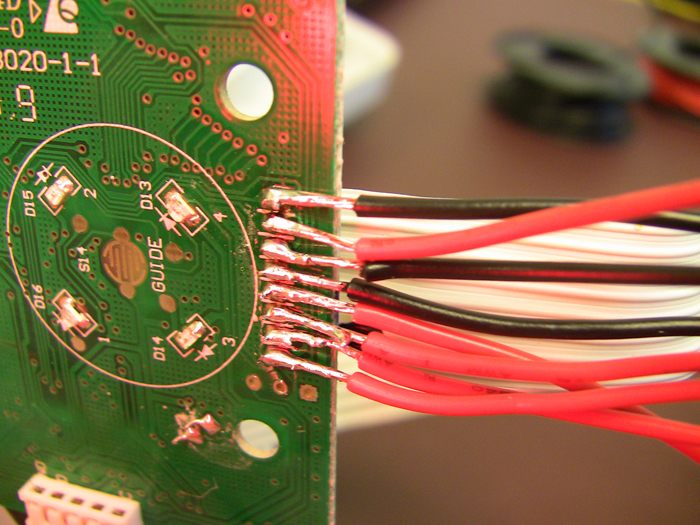
Onto the hardware side… Last week, We opened up the guitar and tested out connections using a multimeter and the “Game Controller” applet in the windows Control panel. Since the guitar is USB, you can plug it into USB, and analyze the button presses in that applet (Virtual buttons light up when you do different things on the guitar). They don’t make it easy. There are 5 buttons, each with 2 touch-sensor type things. When the buttons hits them, a circuit is completed and the button in the game is “pressed.” But, there are only 8 wires coming from the neck of the guitar. After a lot of wire tracing, we realized that some of the connections share a ground, while others don’t. Using the wrong ground results in only half the voltage drop (a drop from 2V down to 0V indicates a short and that the button has been pressed). After figuring out the pinout diagram (I’ll post it later) I was able to solder the appropriate wires onto connections for the guitar boards. I did this in such a fashion that the guitar will still work normally, but the wires will also be routed to the propeller chip that can virtually press the buttons. I soldered on leads that will allow the chip to activate the strum up and down, the whammy bar, and all 5 colored buttons. All of this will be contained inside the guitar. We will cut a hole in the side for a D-sub connection. There will also be a D-sub connection on the sensor bar on the screen. Wires will run between them carrying the information from the photodiodes, and in the other direction providing a 3.3V rail and a grounding wire.
Below are some pictures of the boards with new wires soldered on, and of our current prototyping board for the photodiodes and programming:

 and whammy (right)")
")

7 comments
hey did you use any special programs or anything to devolop it
For reverse engineering, we just used the “game controller” applet in the windows control panel, and the a multimeter.
For some other parts of the project we used the Parallax Propeller programing tool, a schematic design program, etc.
Can you post the pinout diagram. I need it for a project I’m working on
Its available at http://www.mechanizedrock.com
Sorry I know this is an old post but could you please tell me what kind of wire you used (size, material, solid or stranded etc etc.). Thank u very much,
Brian
Hola, tengo una pregunta técnica, el cable (usb) de esta es remplazable, y como se llama? Es para una tarea.
How its call that flat wire wich is 3 in 1 for Up DN and GNU?? Need the name for purchase